Graves and disturbed ground.
A grave shaft can leave a contrast between backfilled soil and the ground around it. Mapping that disturbance helps focus the search for a burial site.
Geophysical software & survey instruments
TERRA — earth. SCRY — to discern what is hidden.TERRASCRY: seeing what the earth hides.
Geophysical instruments and survey software
Graves, unexploded ordnance (UXO), wreckage, and buried structures can leave little to see at the surface. TERRASCRY pairs magnetic and electrical survey instruments with software to help follow those traces underground.

Our mission
A search might start with an old map, a witness account, or a signal that stands out from the surrounding ground. Geophysical surveys add another way to read the site and choose where to look next.
A grave shaft can leave a contrast between backfilled soil and the ground around it. Mapping that disturbance helps focus the search for a burial site.
Buried ordnance can sit among scrap and other debris. Magnetic and electrical readings help map metal responses for investigation by UXO specialists.
An aircraft can leave fragments scattered well beyond the impact point. The pattern of buried metal helps trace the extent of a crash site.
A filled trench or crater can disappear from view while its outline remains in the soil. Differences in the fill offer clues to what was there before.
What shows in a survey depends on the material, depth, and surrounding ground. Readings guide further investigation; confirming remains or identifying and clearing ordnance takes specialist work.
Survey workflow
Start with the site records and a surface survey. Compare the readings, mark areas of interest, and choose the next step. A HIRT probe grid offers a closer investigation where the site calls for it.
01 · Pathfinder
Walk a route with Pathfinder or carry its magnetic sensors beneath a drone. The readings trace changes in the magnetic field along each survey line. In the handheld setup, electromagnetic coils also measure conductivity, including responses from metals that a magnetic survey can miss.
02 · HIRT
HIRT means Hybrid Inductive-Resistivity Tomography. Coils and electrodes sit at known depths on probes arranged across a grid. Taking readings between different probes gives several views through the same ground, which helps build a three-dimensional model.
Probe spacing and depth depend on the site. Suspected hazardous ground requires specialist assessment and clearance before insertion.
Inspect HIRT hardwareInduction · coilsA transmitting coil produces a changing magnetic field. Receiving coils measure the response, providing information about conductive materials between and around the probes.
03 · TERRASCRY software
Follow a response from its place on the map into a cross-section or 3D view. Compare it with nearby readings, terrain, and site records. The measurements stay separate from the model, so you can examine the evidence behind an interpretation.
Explore the softwareSurvey instruments
Pathfinder surveys on foot or by drone. HIRT takes measurements between probes placed around an area of interest. Each gives a different view of what lies below.
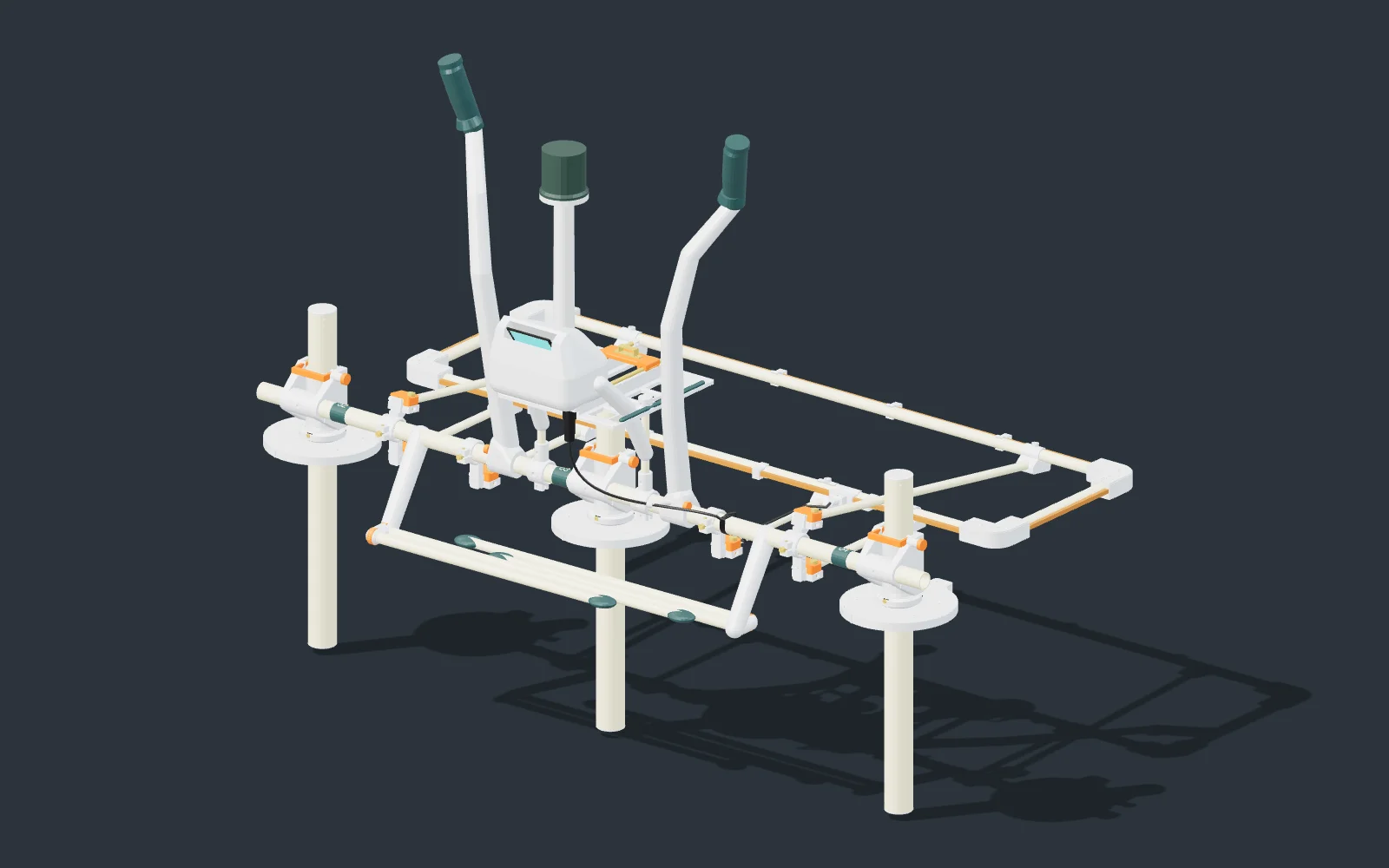
Ground and drone surveying
Magnetic sensors can be carried on foot or beneath a drone. The handheld assembly shown here also pairs them with electromagnetic coils for conductivity readings.
Survey use Walk or fly survey lines and map areas that warrant a closer look.
Discuss Pathfinder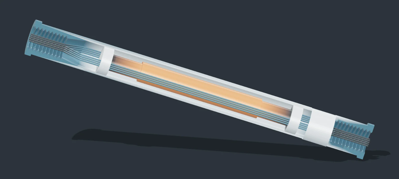

Crosshole subsurface imaging
Coils and electrodes sit at known positions along each probe. Readings taken across the grid help build a three-dimensional model of the ground between them.
Survey use Investigate the shape and extent of a feature within a probe grid.
Discuss HIRTAsk us about instrument specifications and the survey you have in mind.
TERRASCRY software
A signal makes more sense when you can see where it was recorded. Put survey readings beside terrain, aerial imagery, and site records, then examine the ground in 3D.
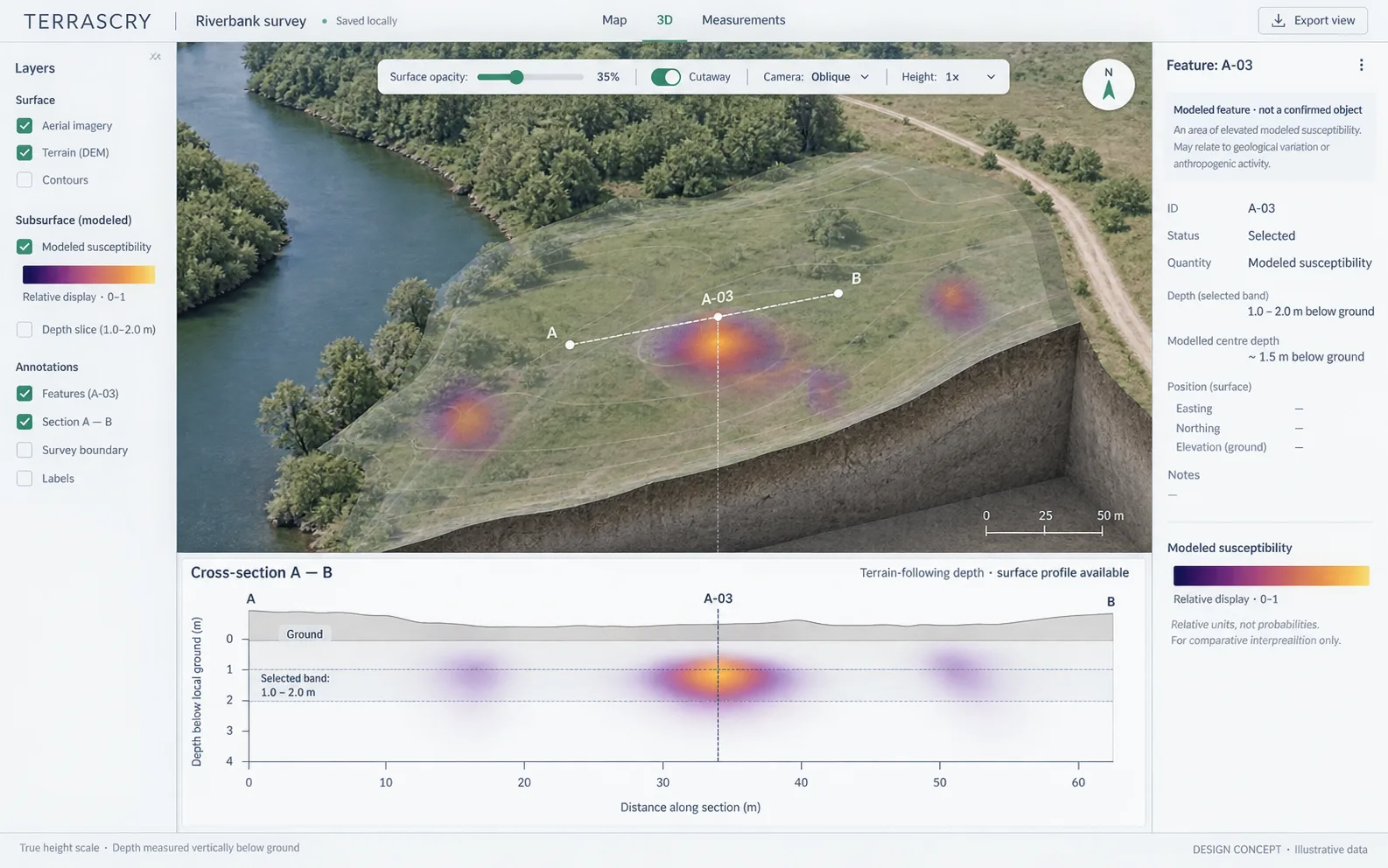
Map, 3D & cross-section
Move between the map, a 3D view, and a cross-section. Compare terrain and imagery with recorded readings and modeled results.
Site preparation
An earlier survey, an aerial photograph, or a marked-up map may explain a feature before anyone takes another reading. Keep those sources beside the measurements and see where the gaps remain.
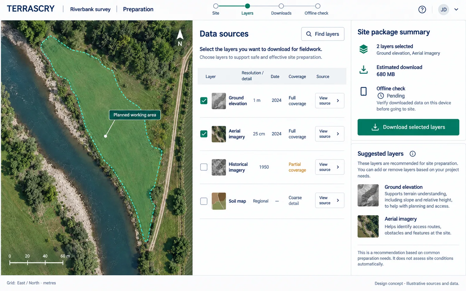
Government, universities & institutions
Whether you’re working on a burial site, surveying former conflict ground, or studying a buried feature, the first conversation is about the question your team needs to answer.
Tell us about the site, the ground conditions, and what you need to find. We can discuss which measurements would help answer the question.
Ask about Pathfinder, HIRT, or TERRASCRY software, including specifications and your team’s purchasing requirements.
Bring a dataset, a field study, or a measurement problem. Let’s discuss the work and what we could learn from it.
Product & partnership inquiries
Tell us what you know about the site and what you hope to find. We’ll talk through the instruments, software, and measurements that fit the work.