Aircraft wreckage and metal debris.
Ferrous and non-ferrous fragments, components, and debris concentrations that can help recovery teams investigate a crash site.
Geophysical software & survey instruments
TERRA — earth. SCRY — to discern what is hidden.TERRASCRY: seeing what the earth hides.
Survey software. Purpose-built instruments.
We are developing geophysical tools for missing-person and aircraft-recovery investigations. Survey the surface, investigate selected areas with a probe grid, and bring the measurements together in a shared view of the ground.
Product development · Evaluation and procurement inquiries welcome

Our mission
We are building TERRASCRY to support the search for missing people and lost aircrews, and the investigation of ground shaped by conflict. The starting point is physical evidence: metal, disturbed soil, and buried features.
Ferrous and non-ferrous fragments, components, and debris concentrations that can help recovery teams investigate a crash site.
Backfilled pits, trenches, possible grave shafts, and changes in soil. These are physical clues to investigate—not confirmation of human remains.
Responses that may warrant assessment for unexploded ordnance (UXO) or other buried metal. Identification and clearance require qualified specialists.
These are intended investigation targets. What a survey can reveal depends on the material, depth, ground conditions, and measurement geometry. Archaeological and research teams can use the same methods to investigate other subsurface questions.
Intended survey workflow
Use TERRASCRY to prepare and review a survey at every stage. Pathfinder is intended to locate areas worth a closer look. Where appropriate, HIRT adds a focused investigation between inserted probes.
01 · Pathfinder
A harness-supported instrument is designed to collect measurements along walking routes. Magnetic gradiometry measures changes in the magnetic field; above-ground electromagnetic coils add information about conductive soil and metal, including non-ferrous metal.
02 · HIRT
HIRT means Hybrid Inductive-Resistivity Tomography. Its design places sensing elements at known positions and depths within a selected area. Measurements across different probe combinations help constrain a three-dimensional model of that volume.
HIRT requires ground insertion. On suspected hazardous ground, qualified assessment and clearance come before insertion. Probe count, spacing, depth, and suitability depend on the site.
Inspect HIRT hardwareInduction · coilsA transmitting coil produces a changing magnetic field. Receiving coils measure the response, providing information about conductive materials between and around the probes.
03 · TERRASCRY software
Survey readings are evidence. A subsurface model is an estimate built from those readings and physical assumptions. TERRASCRY is being developed to compare them with terrain, imagery, and site records—and make uncertainty visible before a team decides what to investigate next.
Explore the softwareThis is the intended instrument-to-software workflow. Hardware qualification, live acquisition, and broader sensor integration remain in development. Suspected hazardous ground requires specialist assessment before any probe insertion.
Survey instruments
Pathfinder addresses handheld survey acquisition. HIRT focuses on crosshole imaging. Both are in development alongside the TERRASCRY software platform.
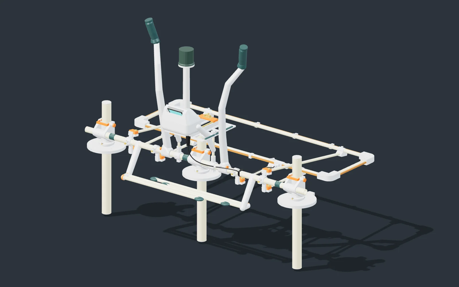
Handheld magnetic and electromagnetic surveying
A handheld survey system being developed for near-surface magnetic gradient and electromagnetic conductivity measurements, with a modular sensor arrangement and georeferenced acquisition.
Intended role Portable acquisition for site-scale geophysical surveys.
Discuss Pathfinder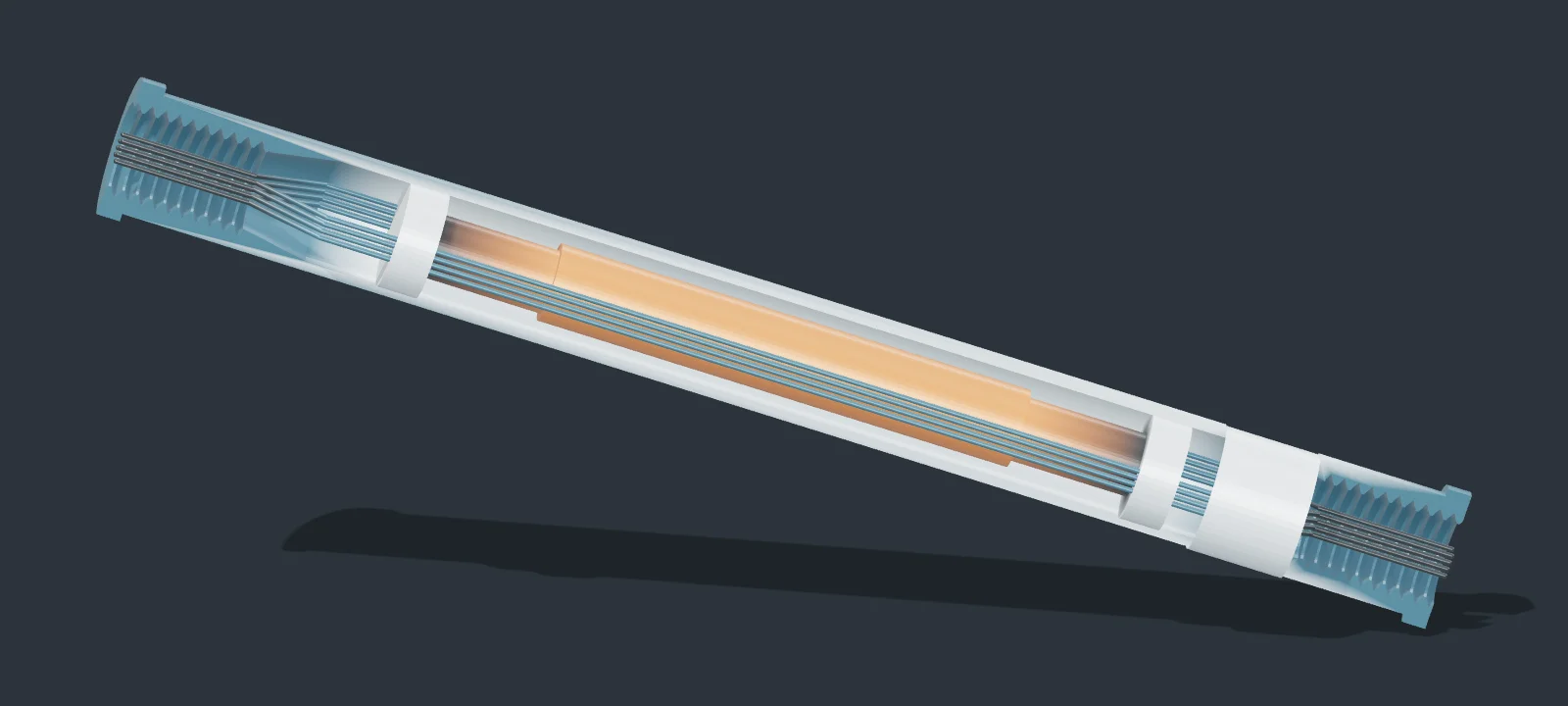

Crosshole subsurface imaging
A dual-channel crosshole tomography system being developed to collect complementary measurements between inserted probes and investigate a focused subsurface volume.
Intended role Targeted subsurface characterization using a distributed probe array.
Discuss HIRTProduct specifications, evaluation availability, and development timelines are discussed directly. CAD renders show development configurations. Bench and field qualification remain to be completed.
TERRASCRY software
A survey workspace for reviewing recorded geophysical data alongside terrain, imagery, and subsurface models. Designed for field review and detailed analysis.
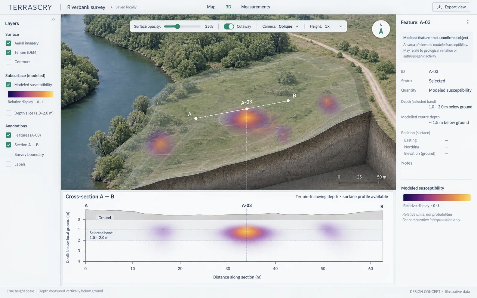
Map, 3D & cross-section
Move between the map, a 3D view, and a cross-section. Compare terrain and imagery with recorded readings and modeled results.
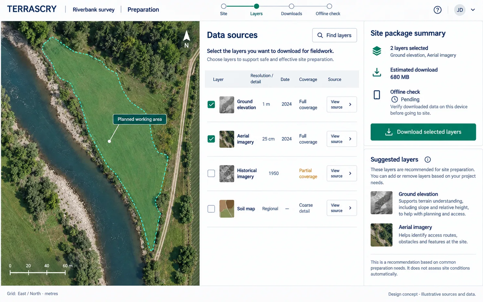
Site preparation
Combine recorded surveys with geographic context. Review source layers and coverage before interpreting the measurements.
In development: recorded magnetic survey workflows, terrain and imagery, local run records, and model inspection. Broader sensor integration and live field acquisition are ongoing work.
Government, universities & institutions
TERRASCRY welcomes discussions with government agencies, research institutions, and commercial survey organizations evaluating subsurface technologies.
Discuss the measurement requirements, data formats, operating environment, and validation evidence your team needs to assess suitability.
Request product information and discuss development schedules, evaluation options, and support requirements before planning a purchase.
Discuss field studies, reference datasets, instrument testing, and methods development.
Product & partnership inquiries
Contact us about TERRASCRY software, Pathfinder or HIRT instruments, technical evaluation, or future procurement.